Starting with Mokka 0.6, several tools were added to process acquisition's data. Depending of your acquisition, you can now process EMG data, detect gait event's from ground reaction forces or create average marker. Some tools already available in previous version of Mokka were also regrouped in this section to be more visible. You will find all these tools in the menu Tools. The following sections give more explanation on some of these tools, and references used for the computation of some parameters or the implementation of some algorithms.
Some internal processing of Mokka are also explained. This processing is necessary for example to compute the Force platform reactions, these components or some extra informations as the direction angle.
Tools
Event
Gait event detection
The detection of gait events is based only on the vertical component of the ground reaction forces and detect events for only one cycle on each force platform. The algorithm works as following:
For each force platform, detect the maximum vertical component. Then, from this maximum:
- Go backward in previous samples and find the sample where the force is below the selected threshold (10 newtons by default).
- If this sample is found then an event "Foot Strike" is created.
- Go forward in next samples and find the sample where the force is below the selected threshold (10 newtons by default).
- If this sample is found then an event "Foot Off" is created.
Marker
Create average marker
The creation of an average marker is based on the current selection of markers. A minimum of two markers are needed to create an average marker. The coordinates of the new markers are built from the average of the coordinates of the current selection of markers. If one markers is occluded during a certain amount of time, then the averaged markers will be also set as occluded.
Analog
The tools proposed to process analog channels are mostly based on the same framework. Based on the options selected, you can directly process the selected analog channels or create new processed analog channels. In this second case the label of the analog channels is kept but a suffix is added.
In case you process analog channels used elsewhere in Mokka (for example the analog channels used for the force platforms), then these other parts are automatically updated. In case of the force platforms, their components are automatically recomputed.
Remove offset
You have two ways to remove offset:
- From an external file (for example an acquisition without subject on force platforms)
- Interactively by selecting the analog channels to process and the frame to use to compute the offset to remove.
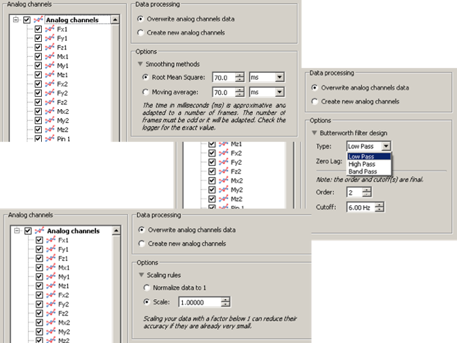
Butterworth filter
You have several option to process your data with Butterworth filters.
You have three kind of filters:
- Low-pass filter: to keep only low frequency (below the cut-off frequency) ;
- High-pass filter: to keep only high frequency (above the cut-off frequency) ;
- Band-pass filter: to keep only frequencies between the given range.
In each case you have to give one(two) cut-off frequency(ies) as well as an order. The order could be represented as the slope of the filter to remove the undesired frequencies.
Finally, the zero-lag option removes the time delay (lag) introduced by the filter. The data will be filtered again in the backward direction. This option is enabled by default and should be activated for all of the processing in biomechanics. The use of this option will adapt the cut-off frequency and the order of the filter to use the given values as final values (i.e. final cut-off frequency and final order). To do so, the order is divided by 2 while the cut-off frequency is scaled. The scale factor is computed as presented in the article Design and responses of Butterworth and critically damped digital filters, Robertson & Dowling, Journal of Electromyography and Kinesiology, 2003.
Note: The implementation of the filters was validated using results computed by the Python module SciPy.signal.filter_design and by Matlab.
Rectification
The rectification takes only the absolute value of the signal.
Scale
You have two ways to scale your data:
- Normalizing your data to 1: The tool takes the maximum absolute value of the signal and divide the entire signal with this value.
- Use of multiplicator coefficient: Multiply your signal by the given coefficient. For example, setting the coefficient to -1.0 will revert your signal.
Smooth
You have two ways to smooth your signal. The smoothing tool can be used for EMG channels when you want to compute their linear enveloppe.
- Root mean square: Compute RMS value of the signal using a window gliding technique
- Moving average: Average a window of the signal at each frame by using a window gliding technique.
Note: Both tools were implemented as described in the book ABC of EMG, A Practical Introduction to Kinesiological Electromyography by Peter Konrad (Version 1.0, April 2005).
Internal data processing
The core of Mokka is based on the library Biomechanical ToolKit. This library implements all the readers/writers for the acquisition file format available in Mokka and the filters to transform acquisition's data (e.g. analogs' data to forceplates to ground reaction wrenches).
Virtual Markers
By default, there is no way to distinguish a real marker from a virtual marker. However a list of markers introduced by Vicon is known to contains data to represent reference frames (as quatro of markers) or center of mass (also projected on the ground). When found these markers are set as virtual markers.
With Mokka 0.6, two metadata (VIRTUAL:MARKERS & VIRTUAL:REFERENCE_FRAMES) were introduced to add easily labels in the list of virtual markers.
- The metadata VIRTUAL:MARKERS consist of a vector of strings where each string contain the label of a marker to set in the list of virtual markers.
- The metadata VIRTUAL:REFERENCE_FRAMES corresponds to an array of strings with n row and 4 columns, where n is the number of reference frames defined.
Note: The current version of BTK does not make any difference between virtual markers and markers used to create a reference frame. This should be introduced later when the definition of segment's pose will exist.
Force platform reactions
Mokka proposes a section Force platform reactions in the Acquisition explorer. Each item corresponds to the reactions measured by a force plaftorm, expressed in the global frame and located to the point of contact between the surface of the platform (working surface) and the object in contact. These results (especially for the moment) are different of the raw signals measured by the force platform. In the case of an AMTI force platform, the raw moments are measured at the sensor origin. These raw signals are visible in Mokka but in the section Analogs.
The sub items Force, Moment and Position are the components of a wrench: A force an moment located to a given position. This position is called the Point of Wrench Application (PWA). For Gait, the PWA is very similar to the COP, but doesn't assume any null horizontal forces. The computation of PWA is based on the paper of Shimba T. An estimation of center of gravity from force platform data. Journal of Biomechanics, 1984, 17(1), 53–60.
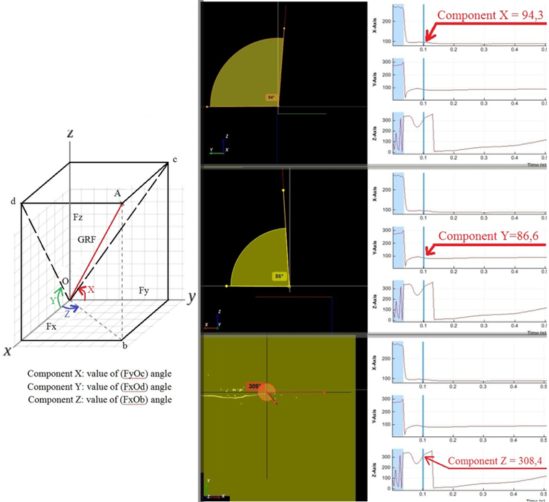
Direction Angle
A fourth sub item called Direction angle is also listed. It measures the angles of the ground reaction forces relative to the global frame. The exact definition of each component is listed below:
- Component X is given by the angle between projection of GRF vector in zOy plane and starting from the Oy axis ;
- Component Y is given by the angle between projection of GRF vector in xOz plane and starting from the Ox axis
- Component Z is given by the angle between projection of GRF vector in yOz plane and starting from the Ox axis.
The following figure illustrates the definition of the direction angle as well as these components.